Fieldbus
Before Modbus was invented the issue of connection-oriented control was addressed, where each contact had to be individually wired, requiring two wires per contact. As the amount of information to be transmitted increased, the complexity of the wiring also grew.
The solution came with the introduction of the fieldbus, whose basic principle is similar to Morse code. Both transmitters and receivers must use the same coding system (protocol).
Modbus
Modbus was developed by Modicon in 1979. The general data-model has not changed since them. Modbus-TCP is a standard since 2007.
Modbus includes:
- Modbus RTU – serial data technology – RS485
- Modbus Acsii – serial data technology – RS485, RS232
- Modbus-TCP – RJ45
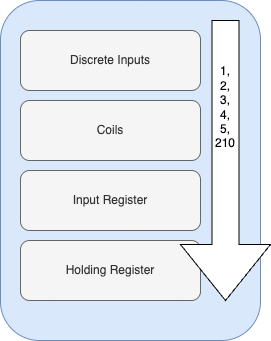
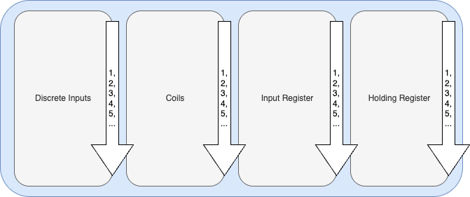
Datamodel
| Datatype | Length | Type | Description |
|---|---|---|---|
| Discretes Inputs | 1 Bit | Read | Digital Input |
| Coils | 1 Bit | Rad and Write | Digital Output |
| Input Registers | 16 Bit | Read | Analog Input |
| Holding Registers | 16 Bit | Read and Write | Analog Output |
Examples
Discretes Inputs: open/closed
Coils: on/off
Input Registers: -20 -80°C
Holding Register: 0-100%
Discrete Input
The discrete input has a length of 1 Bit. The possible access to this data-type is just read. Corresponds to a digital input.
Example
The PLC calls the state of n inverter.
Possible states: true/false – 0/1
Corresponds to the Boolean data type in PLC programming
Coils
Coils also have a length of 1 Bit, the difference to Discrete Inputs is, that the access to this data-type is read and write. This allows you to change information of this data type. This provides digital output.
Example
The PLC calls the state of n switch relay.
Possible states: true/false – 0/1
Corresponds to the Boolean data type in PLC programming
Input Register
Is an analog data-type, as the name input says, it has read access to the data. The size is 16 Bit which corresponds to 2 Bytes and can therefore map data from 0-65535
Example
Temperature or humidity sensor.
How exactly the transmitted values are to be interpreted must be looked up in the manual of the specific venvor.
Holding Register
Last but not least, the analog output. Also with a length of 16 Bit but with read and write access to the data.
Example
The power of a servomotor which is to be set in %.
Data Points
It’s important to refer to the manufacturer’s instructions here. It describes how the data points are provided. Each piece of information that a device makes available via Modbus is assigned a register number and a data type.
- Register number
- Data type
- (Read/Write access)
Single Data-Areas
A distinction is made here between a large memory area in which all information is listed one after the other.
It should be noted that not all data points have to be listed directly one after the other; there may well be larger gaps. They do not have to be grouped; for example, discrete inputs can come first, then coils and then discrete inputs again. This depends on the manufacturer’s specification.
Separate Data Areas
However, it is possible for each data type to be assigned its own memory area. This means that there can be double data points, e.g. 1 as a coil and to the input register. And here only the function code distinguishes which data type is used.
But, this variant is not as widespread as a single data area.
Function Codes
Describe the actions to be performed read, write, read and write. Compatible with a Morse code table. A distinction is made between the following types of function code. This function codes are specified by the Modbus organisation.
Public Function Codes
This function codes are specified by the Modbus organisation, public and documented.
Enabled Area: 1-65;72-100;110-127
| FC | Data-type | Action |
|---|---|---|
| FC1 | Coil | Reading of one or more digital Outputs |
| FC2 | Discrete Input | Reading of one or more digital Inputs |
| FC3 | Holding Register | Reading of one or more analog Outputs |
| FC4 | Input Register | Reading of one or more analog Inputs |
| FC5 | Coil | Write of one digital Output |
| FC6 | Holding Register | Write of one analog Output |
| FC15 | Coil | Write of more digital Output |
| FC16 | Holding Register | Write of more analog Output |
User-Defined Function Codes
Developed by vendors and users, more company internal usage.
Enabled Area: 65-72;100-110
Reserved Function Code
Used by old products (legacy devices)
Example FC-1 in detail
Reads out the status of one or more coils (digital outputs). Cannot change the digital output but you can query the current status.
Access: Read
Data-Type: Coils
Count: 1-2000
Request
A request consists of three components:
| Request | Size | Example hexa | Example dezimal |
|---|---|---|---|
| Function Code | 1 Byte | 0x01 | 1 |
| Modbusregister (Startregister) | 2 Bytes | 0x007D | 55 |
| Count of reading Coils | 1 Byte | 0x0001 | 1 |
Answer
| Answer | Size | Example hexa | Example dezimal |
|---|---|---|---|
| Function Code | 1 Byte | 0x01 | 1 |
| Byte Count | 2 Bytes | 0x0001 | 1 |
| Status der Coils | 1 Byte | 0x01 | 1 |
The byte count indicates exactly how large the status of the coils is (1 byte = 8 bits = 8 possible states)
Convert decimal notation and hex notation to binary to explain the value.
The first byte is responsible for the lowest registers.